Fire Prevention Upgrades
Nov 28, 2024
The QIDI X-Max 3 is a critical part of our 3D printing fleet, with more than 15 of these units running around the clock to produce a variety of materials, including high-temperature options like ASA and PC. These machines work harder than a typical user’s setup, and over time, we discovered a concerning issue: a chip on the toolhead board that regulates power to the extruder heating element tends to fail under continuous use. When it burns out, the heating element receives unregulated power, causing the hot end to dangerously overheat, potentially leading to a fire and printer failure.
Upon investigation, we noticed that the factory setup uses a small fan to cool the chip, but the airflow is blocked by a rubber band wrapped around the board to hold the USB in place, even though the USB is already secured with a bracket. To address this, we removed the rubber band, replaced the rear cover with one that accommodates a larger fan, and added a heat sink to the chip for improved cooling. For added safety, we installed a relay inline between the mainboard and the toolhead. This relay, triggered by Klipper on shutdown, completely cuts power to the toolhead, preventing overheating if the chip fails.
Below, we outline the steps we took to enhance the safety and reliability of the QIDI X-Max 3. Please proceed with caution when working on your printers and handling electrical components, and note that we do not assume responsibility for any issues arising from following this guide.
QIDI X-Max 3 Fire Prevention Upgrades
1. Set Up the Toolhead
Parts Required
ASA Printed Toolhead Cover with Room for Larger Fan
Download the model here.
Printing Tip: Use vertical orientation to keep layer lines perpendicular to the mounting holes to prevent breakage.
2 - M2.5x10mm Button Head Bolts
25x25x7mm 5V Fan (Link)
7x7x4mm Heat Sink (Link)
Steps
Remove the Toolhead Rear Cover
Unscrew the 4 - M2.5 bolts holding the rear cover.
Unplug the fan connected to the stock cover.
Carefully remove or cut off the rubber band that covers the USB bracket.
Install the Larger Fan
Place the 25x25x7mm fan into the ASA-printed cover (ensure the air blows in).
Attach the fan using 2 - M2.5x10mm button head bolts.
Bolts should go through the fan from the inside and screw into the cover.
Keep the fan wires tidy using zip ties on the rear cover.
Clean and Apply Heat Sinks
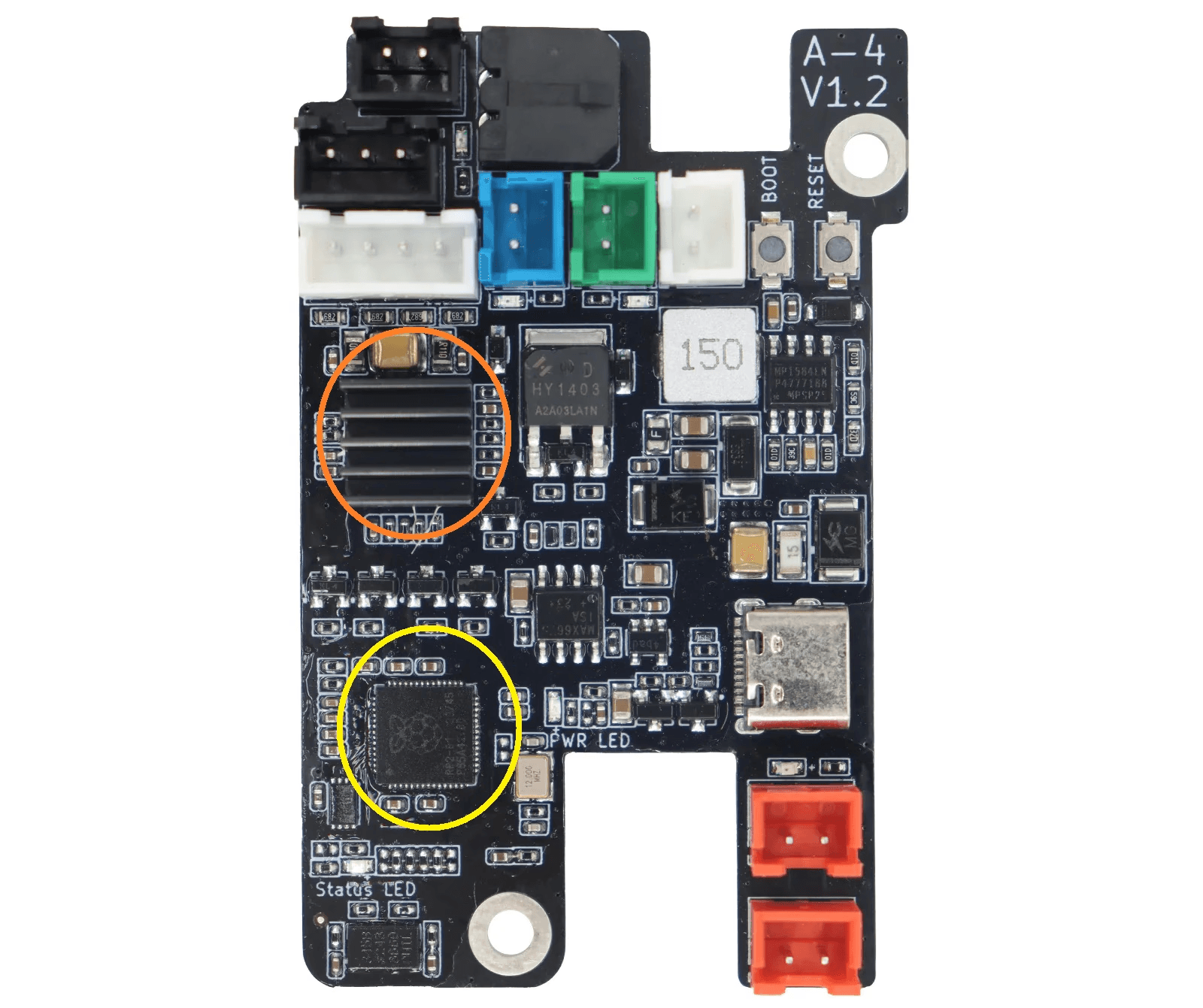
Identify the chips:
Orange Circle: Should already have a heat sink.
Yellow Circle: Clean the chip and apply a new heat sink.
Attach the heat sink using the sticky back or thermal glue.
Reassemble
Plug in the new fan, top red XH connector.
Reinstall the cover with the 4 bolts.

2. Install Emergency Power Cut-Off Relay
Parts Required
Solid State DC Relay (Link)
22-AWG Wire
2-pin XH Connector
Double sided mounting tape
Steps
Access the Main Board
Remove the back cover of the QIDI X-Max 3.
Unplug the fan on the cover (usually Fan 2) and note the pin location.
Locate and unplug the USB connected to the toolhead (top left corner of the board).
Prepare the Relay
Find a suitable position (Lower right corner of the cavity works well).
Mock the relay’s position to ensure the USB cable can reach.
Modify the USB Cable
Cut back the USB cable covering to expose the wires.
Do not damage the insulation on any of the wires within the main covering.
Isolate the red power wire, cut it, and strip both ends (~10mm).
Prepare Trigger Wires
Create a set of two wires (red and black) with a 2-pin XH connector on one end.
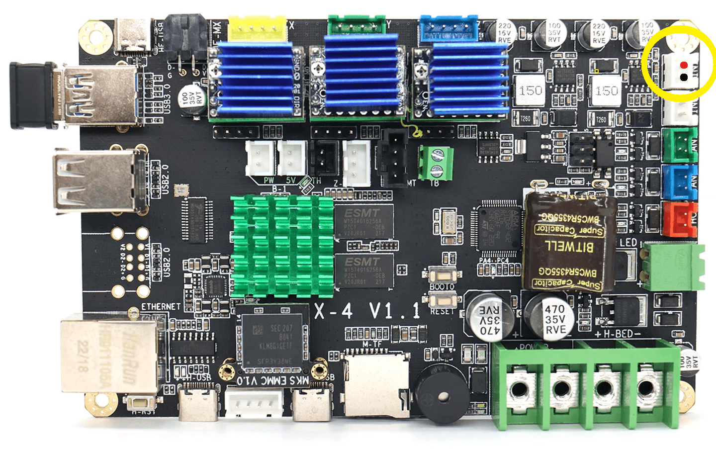
Ensure the wires are long enough to reach from the FAN 3 terminal (see yellow circle) to the relay.

Wire the Relay
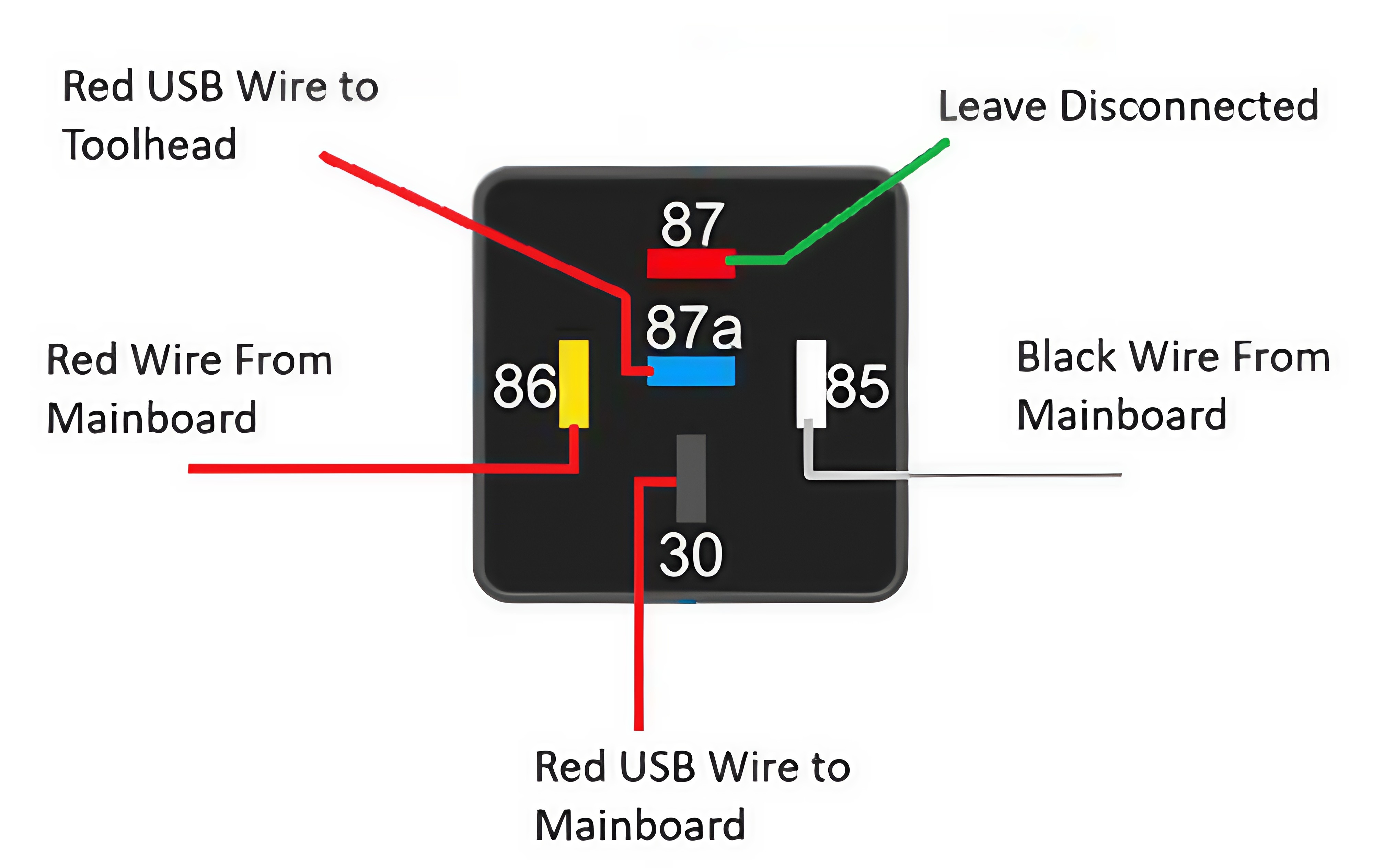
Red Wire (Toolhead): Connect to Blue Wire from relay.
Red Wire (Mainboard): Connect to Black Wire from relay.
Red Trigger Wire: Connect to Yellow Wire from relay.
Black Trigger Wire: Connect to White Wire from relay.

Mount the Relay
Secure the relay with mounting tape.
Solder and heat-shrink all connections.
Plug in the Trigger
Connect the trigger wires to FAN 3 (ensure correct orientation).
Close Up the Machine
Route wires neatly.
Plug in the fan on the cover (Fan 2).
Reattach the back cover.
3. Set Up Klipper
Steps
Power On the Printer
Ensure the boot screen fully loads.
Access Configuration Files
Open the Fluidd interface by entering the printer’s IP address in your browser.
Navigate to printer.cfg.
Add Safety Function
In a suitable place within the file, add:
Adjust Extruder Max Temperature
In the extruder section, set max_temp to 300 (default is 360).
Save and Restart
Save changes and restart the machine.
4. Verify Your Install
Check Toolhead Cooling
Ensure the new fan is operating correctly.
It should be spinning if the machine is booted up and the hotend is heating.
Confirm Relay Function
Verify the relay cuts power appropriately during an emergency.
In your machine’s console, type the command:
The machine should lose connectivity to the toolhead and go into an error state.
Temperature Limits
Confirm the max temperature setting in Klipper is set.


